Build an Apple Homekit Temperature and Humidity Sensor with ESP-01S and DHT22.

|
|
DIY Homekit Temperature and Humidity Sensor |
Recently, the weather in Malaysia has been getting hotter. But, how hot is my living room? To understand the temperature and humidity in my living room, build a temperature and humidity sensor comes to mind. Also, I want the sensor to join the Apple Homekit, so the reading from the sensor can display on my iPhone or ask Siri to read for me.
Hardware:
First, I ordered all the parts from the online store.
- ESP-01 USB Programmer with CH340C
- ESP-01S
- DHT22 Temperature and Humidity Sensor Module
- Ywrobot Power BM V2 (Power supply module)
- 9V power adapter.
- 400 pin breadboard.
- 3 male to female jumper wire.
- 2 male to male jumper wire.
Software to Download:
Second, I will use esp-homekit-devices and esptool open source projects from
Github. Also, Python and CH340 driver for esp-01 USB programmer.
- Python: https://www.python.org/downloads/release/python-392/
- esptool.py: install via pip
- CH340 driver: http://www.wch.cn/download/CH341SER_ZIP.html
- fullhaaboot.bin: https://github.com/RavenSystem/haa/releases/latest/download/fullhaaboot.bin
Install Software and Driver:
- Install Python. Don't forget to check the "add Python to PATH".
- Open the command prompt, type "pip install esptool" to install esptool, and click enter.
- Install CH 340 driver.
Flash Firmware to ESP-01S:
- Plug the ESP-01S into USB Programmer. After, plug the USB Programmer into the computer.
-
Check the USB Programmer port. Open Device Manager > Ports(COM & LPT) > USB-SERIAL CH340 (COM4), COM4 is the port.
Check the USB Programmer Port
-
Open the command prompt, type in
esptool.py -p /dev/<your_ESPPort> --baud 115200 write_flash -fs 1MB -fm dout -ff 40m 0x0 fullhaaboot.bin
Replace the <your_ESPPort> to the correct port. For example COM4. Press Enter to flash the firmware to ESP-01S. - Don't remove the USB Programmer and the ESP-01S. The ESP-01S needs power and time to initiate the firmware; it takes about 2-4 mins.
Setup ESP-01S
ESP-01S is ready to connect. You can use your iPhone to search for the Wi-Fi
name starting with "HAA-xxxxxx" and connect to the Wi-Fi. Once the iPhone is
connected to ESP-01S, the iPhone will pop out a setup page automatically. If
the setup page does not pop up, you can type 192.168.4.1:4567 on the Safari
browser. On the setup page, it needs to set up the Wi-Fi and JSON Config. The
Wi-Fi configuration is very intuitive, the JSON config a bit tricky. The JSON
Config tells the firmware how to work with the sensor/switch or button. Copy
below JSON and paste to the setup page JSON config section.
Here is my JSON Config:
{
    "a":[
        {
            "t":24,
            "g":0,
            "n":2
        }
    ]
}
let me explain my JSON:
- "a": means accessory; all the sensors, switches, or buttons can declare in the "a" array. For this project, the ESP-01S only attaches a sensor. So, the "[" and "]" will only have one "{" and "}" object.
- Inside the object, "t":24 means temperature and humidity sensor attached. "g":0 means the sensor attached to GPIO0, ESP-01S can communicate with the sensor via this pin. "n":2 means the temperature and humidity sensor is a DHT22, the firmware knows how to communicate with it.
The open-source project: esp-homekit-devices provides a very detailed JSON config guide, so if you are interested in all the configurations, please visit esp-homekit-devices Wiki. After completing all the settings, click the save button to save it. The ESP-01S is ready to go.
Put all together
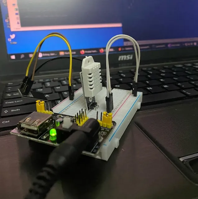
Now, all the parts have to be plugged into the breadboard to make it work. The first thing is the YWROBOT Power MB V2 (power supply module) provides 2 voltages on 2power rails on the breadboard. I configure one side to 3.3V and the other side as 5V, plug into the breadboard. Next, I use the two male-to-female jumper wires, the male pins plug into the 3.3 V power rail on the breadboard, and the female pins plug into ESP-01S 3V3 and GND pin. Be aware of the positive terminal and negative terminal; the positive terminal should connect to the ESP-01S 3V3 pin, the negative terminal connected to the GND pin. The other male-to-female jumper connects between the ESP-01S IO0 pin and one of the holes in the breadboard terminal stripe.
The DHT22 has a 3 pin; both sides of the pins are positive and negative terminals, the middle pin for data to communicate with ESP-01S. On the breadboard, I use 2 male-to-male jumper wires to connect the 5V power rail, the other side connects to the DHT22. The DHT22 middle pin and the ESP-01S IO0's jumper wire should plug in the same row in the terminal stripe. Until here, the 9V power adapter is ready to plug into the power supply module and turn it on. All the parts on the breadboard should work fine without any smoke or fire.
Lastly, download the Home App from App Store to add the accessory to the Home
App.
-
Open Home > tap "add accessory" > Scan QR Code > tap "Add to Home"

Homekit QR Code (From: esp-homekit-device wiki) 
Normal Code (From: esp-homekit-device wiki) - Home App will connect to the accessory and pop out with "Uncertified Accessory", just tap "Add Anyway" to continue.
-
Once Home App is connected to the Homekit sensor, it will pop out to set up
the sensor location and sensor name, tap "Continue" and "Done".
Presently, you can check the temperature and humidity on your iPhone. "Hey,
Siri. Check my living room temperature." or "Hey, Siri. Check my living room
humidity." let Siri read the number for you.
Final result:


%20with%20Rechargeable%20NiMH%20batteries%20and%20HT7833%20voltage%20regulator%20cover.webp)
