Arduino + ESP8266 + RC522 RFID Module to save RM 100 replacement fee for my RFID access card.
![]() |
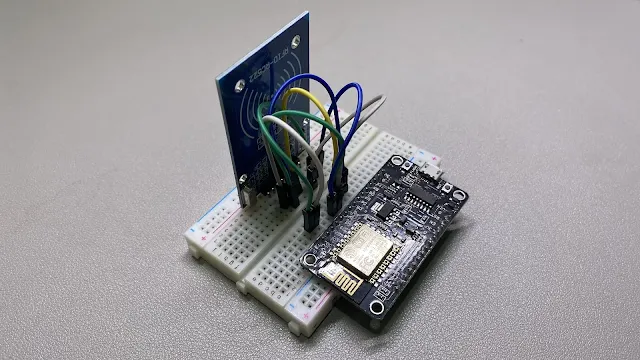
ESP8266 connects with RC522 RFID module. |
My RFID card just not working anymore. We passed the access card to the management and let them find the issue. They told us the card needed RM 100 to replace it.
My inner thought was like: WHAT ???!!!!! SO EXPENSIVE!!!
Since I still have another working access card and know a bit about Arduino, maybe I could use Arduino to clone a new card.
Let's do it.
RFID Card Frequency: 13.56 MHz or 125 KHz?
First, we need to figure out the access card technology. I try to use my phone's NFC to sense the access card, but nothing happens. I believe the access card uses RFID technology. However, I'm not sure about which frequency. I guess the access card could be 13.56MHz or 125KHz.
Therefore, I sneak to the access door and look up the RFID reader. After that, I can confirm the access card using MIFARE 13.56MHz.
Pick-Up Part
The next thing to do is start picking up some parts. I already have an ESP8266, so the only thing left is the RFID module.
I pick the classic MFRC522 RFID module that supports read and write data for the MIFARE 13.56Mhz RFID card. It costs RM 10, including an RFID module with soldered pins and two RFID cards.
![]() |
ESP8266 |
![]() |
RC522 RFID Module |
Wire-up ESP8266 and RC522 RFID Module
Now, we can wire up all the parts together according to below:
------------ ---------- | ESP8266 | RC522 | ------------ ---------- | D1(GPIO5) | RST | ------------ ---------- | D2(GPIO4) | SDA | ------------ ---------- | 3V | 3.3V | ------------ ---------- | GND | GND | ------------ ---------- | D5(GPIO14) | SCK | ------------ ---------- | D6(GPIO12) | MISO | ------------ ---------- | D7(GPIO13) | MOSI | ------------ ----------
Coding
After wiring up everything, we can start coding(Not really).
Install MFRC522 Library
- Open Arduino
- Go to Sketch, Include Library, and click Manage Libraries...
- Search "MFRC522" and install the library.
Open and Upload Dumpinfo Sketch.
- Go to File -> Example -> MFRC522
- Click Dumpinfo
This Dumpinfo is a sketch(program) to read the RFID access card. Change the RST_PIN to 5 and SS_PIN to 4.
Then, we upload the program into the ESP8266 and tap the functioning access card on the MFRC522 module to retrieve the data. We can open the serial monitor to view all the data.
/* | |
* -------------------------------------------------------------------------------------------------------------------- | |
* Example sketch/program showing how to read data from a PICC to serial. | |
* -------------------------------------------------------------------------------------------------------------------- | |
* This is a MFRC522 library example; for further details and other examples see: https://github.com/miguelbalboa/rfid | |
* | |
* Example sketch/program showing how to read data from a PICC (that is: a RFID Tag or Card) using a MFRC522 based RFID | |
* Reader on the Arduino SPI interface. | |
* | |
* When the Arduino and the MFRC522 module are connected (see the pin layout below), load this sketch into Arduino IDE | |
* then verify/compile and upload it. To see the output: use Tools, Serial Monitor of the IDE (hit Ctrl+Shft+M). When | |
* you present a PICC (that is: a RFID Tag or Card) at reading distance of the MFRC522 Reader/PCD, the serial output | |
* will show the ID/UID, type and any data blocks it can read. Note: you may see "Timeout in communication" messages | |
* when removing the PICC from reading distance too early. | |
* | |
* If your reader supports it, this sketch/program will read all the PICCs presented (that is: multiple tag reading). | |
* So if you stack two or more PICCs on top of each other and present them to the reader, it will first output all | |
* details of the first and then the next PICC. Note that this may take some time as all data blocks are dumped, so | |
* keep the PICCs at reading distance until complete. | |
* | |
* @license Released into the public domain. | |
* | |
* Typical pin layout used: | |
* ----------------------------------------------------------------------------------------- | |
* MFRC522 Arduino Arduino Arduino Arduino Arduino | |
* Reader/PCD Uno/101 Mega Nano v3 Leonardo/Micro Pro Micro | |
* Signal Pin Pin Pin Pin Pin Pin | |
* ----------------------------------------------------------------------------------------- | |
* RST/Reset RST 9 5 D9 RESET/ICSP-5 RST | |
* SPI SS SDA(SS) 10 53 D10 10 10 | |
* SPI MOSI MOSI 11 / ICSP-4 51 D11 ICSP-4 16 | |
* SPI MISO MISO 12 / ICSP-1 50 D12 ICSP-1 14 | |
* SPI SCK SCK 13 / ICSP-3 52 D13 ICSP-3 15 | |
* | |
* More pin layouts for other boards can be found here: https://github.com/miguelbalboa/rfid#pin-layout | |
*/ | |
#include <SPI.h> | |
#include <MFRC522.h> | |
#define RST_PIN 5 // Configurable, see typical pin layout above | |
#define SS_PIN 4 // Configurable, see typical pin layout above | |
MFRC522 mfrc522(SS_PIN, RST_PIN); // Create MFRC522 instance | |
void setup() { | |
Serial.begin(9600); // Initialize serial communications with the PC | |
while (!Serial); // Do nothing if no serial port is opened (added for Arduinos based on ATMEGA32U4) | |
SPI.begin(); // Init SPI bus | |
mfrc522.PCD_Init(); // Init MFRC522 | |
delay(4); // Optional delay. Some board do need more time after init to be ready, see Readme | |
mfrc522.PCD_DumpVersionToSerial(); // Show details of PCD - MFRC522 Card Reader details | |
Serial.println(F("Scan PICC to see UID, SAK, type, and data blocks...")); | |
} | |
void loop() { | |
// Reset the loop if no new card present on the sensor/reader. This saves the entire process when idle. | |
if ( ! mfrc522.PICC_IsNewCardPresent()) { | |
return; | |
} | |
// Select one of the cards | |
if ( ! mfrc522.PICC_ReadCardSerial()) { | |
return; | |
} | |
// Dump debug info about the card; PICC_HaltA() is automatically called | |
mfrc522.PICC_DumpToSerial(&(mfrc522.uid)); | |
} |
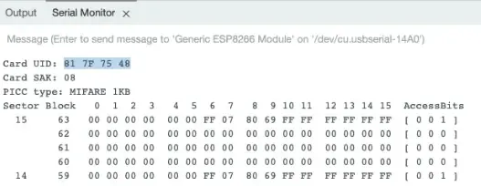
Here is my card info. I think the main thing is UID. Save the UID for later.
![]() |
Serial Monitor shows the functioning access card's UID read from the RC522. |
Open and Upload ChangeUID Sketch.
- Go to File -> Example -> MFRC522
- Click ChangeUID
The ChangeUID is a sketch to write the UID into the RFID card. We need to replace the value on line 36 with our functioning RFID access card's UID. Also, change the RST_PIN to 5 and SS_PIN to 4. Then, upload it to the ESP8266.
/* | |
* -------------------------------------------------------------------------------------------------------------------- | |
* Example to change UID of changeable MIFARE card. | |
* -------------------------------------------------------------------------------------------------------------------- | |
* This is a MFRC522 library example; for further details and other examples see: https://github.com/miguelbalboa/rfid | |
* | |
* This sample shows how to set the UID on a UID changeable MIFARE card. | |
* | |
* @author Tom Clement | |
* @license Released into the public domain. | |
* | |
* Typical pin layout used: | |
* ----------------------------------------------------------------------------------------- | |
* MFRC522 Arduino Arduino Arduino Arduino Arduino | |
* Reader/PCD Uno/101 Mega Nano v3 Leonardo/Micro Pro Micro | |
* Signal Pin Pin Pin Pin Pin Pin | |
* ----------------------------------------------------------------------------------------- | |
* RST/Reset RST 9 5 D9 RESET/ICSP-5 RST | |
* SPI SS SDA(SS) 10 53 D10 10 10 | |
* SPI MOSI MOSI 11 / ICSP-4 51 D11 ICSP-4 16 | |
* SPI MISO MISO 12 / ICSP-1 50 D12 ICSP-1 14 | |
* SPI SCK SCK 13 / ICSP-3 52 D13 ICSP-3 15 | |
* | |
* More pin layouts for other boards can be found here: https://github.com/miguelbalboa/rfid#pin-layout | |
*/ | |
#include <SPI.h> | |
#include <MFRC522.h> | |
#define RST_PIN 5 // Configurable, see typical pin layout above | |
#define SS_PIN 4 // Configurable, see typical pin layout above | |
MFRC522 mfrc522(SS_PIN, RST_PIN); // Create MFRC522 instance | |
/* Set your new UID here! */ | |
//#define NEW_UID {0xDE, 0xAD, 0xBE, 0xEF} | |
#define NEW_UID {0x81, 0x7F, 0x75, 0x48} | |
MFRC522::MIFARE_Key key; | |
void setup() { | |
Serial.begin(9600); // Initialize serial communications with the PC | |
while (!Serial); // Do nothing if no serial port is opened (added for Arduinos based on ATMEGA32U4) | |
SPI.begin(); // Init SPI bus | |
mfrc522.PCD_Init(); // Init MFRC522 card | |
Serial.println(F("Warning: this example overwrites the UID of your UID changeable card, use with care!")); | |
// Prepare key - all keys are set to FFFFFFFFFFFFh at chip delivery from the factory. | |
for (byte i = 0; i < 6; i++) { | |
key.keyByte[i] = 0xFF; | |
} | |
} | |
// Setting the UID can be as simple as this: | |
//void loop() { | |
// byte newUid[] = NEW_UID; | |
// if ( mfrc522.MIFARE_SetUid(newUid, (byte)4, true) ) { | |
// Serial.println("Wrote new UID to card."); | |
// } | |
// delay(1000); | |
//} | |
// But of course this is a more proper approach | |
void loop() { | |
// Reset the loop if no new card present on the sensor/reader. This saves the entire process when idle. And if present, select one. | |
if ( ! mfrc522.PICC_IsNewCardPresent() || ! mfrc522.PICC_ReadCardSerial() ) { | |
delay(50); | |
return; | |
} | |
// Now a card is selected. The UID and SAK is in mfrc522.uid. | |
// Dump UID | |
Serial.print(F("Card UID:")); | |
for (byte i = 0; i < mfrc522.uid.size; i++) { | |
Serial.print(mfrc522.uid.uidByte[i] < 0x10 ? " 0" : " "); | |
Serial.print(mfrc522.uid.uidByte[i], HEX); | |
} | |
Serial.println(); | |
// Dump PICC type | |
// MFRC522::PICC_Type piccType = mfrc522.PICC_GetType(mfrc522.uid.sak); | |
// Serial.print(F("PICC type: ")); | |
// Serial.print(mfrc522.PICC_GetTypeName(piccType)); | |
// Serial.print(F(" (SAK ")); | |
// Serial.print(mfrc522.uid.sak); | |
// Serial.print(")\r\n"); | |
// if ( piccType != MFRC522::PICC_TYPE_MIFARE_MINI | |
// && piccType != MFRC522::PICC_TYPE_MIFARE_1K | |
// && piccType != MFRC522::PICC_TYPE_MIFARE_4K) { | |
// Serial.println(F("This sample only works with MIFARE Classic cards.")); | |
// return; | |
// } | |
// Set new UID | |
byte newUid[] = NEW_UID; | |
if ( mfrc522.MIFARE_SetUid(newUid, (byte)4, true) ) { | |
Serial.println(F("Wrote new UID to card.")); | |
} | |
// Halt PICC and re-select it so DumpToSerial doesn't get confused | |
mfrc522.PICC_HaltA(); | |
if ( ! mfrc522.PICC_IsNewCardPresent() || ! mfrc522.PICC_ReadCardSerial() ) { | |
return; | |
} | |
// Dump the new memory contents | |
Serial.println(F("New UID and contents:")); | |
mfrc522.PICC_DumpToSerial(&(mfrc522.uid)); | |
delay(2000); | |
} |
The Problem
At first, I thought the RFID cards from the RC522 module could change UID. When I tap it on the RC522 module, the serial monitor prompts errors.
![]() |
Serial Monitor shows error while try to change UID on read-only RFID card. |
After some research, I found out I needed the RFID card can be written through all storage sectors.
I ordered from an online store and received the new RFID card after two weeks. Then, I tap the new RFID card on the RC522 module. The serial monitor shows everything ok.
![]() |
Storage sectors from the new RFID access card. |
Looking at the storage sectors, we can see the first to fourth sectors are the UID. The fifth sector is the checksum. The rest is the manufacturer's info.
So, I think this card should work.
Test the RFID access card.
I tested the RFID access card at the side and the main door, and both working without issues.
**Check the result in my video at 3:05.
Conclude
In the end, I saved around RM 70 by cloning the access card myself.
Cost breakdown:
- ESP8266 - RM16
- RC522 RFID Module - RM 10
- RFID Card - RM 3
Maybe I can start my business by cloning the access card. I know. I'm just joking.