DIY a YouTube Subscriber Counter with ESP-01S (ESP8266), SSD1306 0.96 inch 128x64 I2C OLED Display, and Arduino IDE.

|
| YouTube Subscriber Counter |
I have a Mandarin-speaking YouTube channel, making videos about DIY projects, IoT, Hackintosh, and PC tips. Recently, I've felt low on motivation to create new content. So, I decide to make a YouTube subscriber counter to remind me that someone is waiting for my new video(I hope so...).
Preparation
Hardware
I planned to use the hardware I currently have to build the YouTube subscriber counter.
- ESP-01S Development Board
- ESP-01 USB Programmer
- SSD1306 0.96 inch 128x64px I2C OLED Display
- Breadboard
- Jumper Wires
- YwRobot Power MB V2
- 9V Power Adapter
 |
| USB Programmer, 0.96 inches I2C OLED Display and ESP-01S |
 |
| 9V Power Adapter, YwRobot Power MB V2, Breadboard, and Jumper Wires |
Install CH340 driver
The ESP-01 USB Programmer uses the CH340 chip to convert the USB to the serial interface. It needs to install a driver to function correctly.
We can download and install the driver from the manufacturer's website. The driver installation is very straightforward; click the "Next" button until the installer asks you to restart your computer.
Install Arduino IDE
You can refer to my previous article about setting up the Arduino IDE for ESP8266.
Get the YouTube Data API Key
Once the Arduino IDE installation is completed, we can put it aside and get the YouTube Data API key first. Here, we need to do 2 things. First, enable the YouTube Data API, so we can use the API function. Second, create a credential key to access the API.
Head to the Google Developer console, then log in to your Google account that links with your YouTube channel.
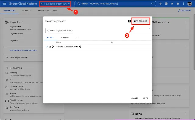
Create a new project and name the project as you wish.
 |
| Create a new project in the Google Cloud Platform |
 |
| Name the new project |
After the project creation, we need to select the project.
 |
| Select the project created just now. |
Enable YouTube Data API
Click the Navigation menu -> scroll down and hover APIs & Services -> click in the Library -> search for YouTube Data API v3 and click it -> click the Enable button.
 |
| Go to the Library |
 |
| Select the YouTube Data API v3 |
 |
| Click the Enable button |
Create Credential Key
Click the Navigation Menu -> scroll down and hover APIs & Services -> click in the Credentials -> click the CREATE CREDENTIALS -> select API key -> to save the API key that will be used later.
 |
| Go to the Credentials |
 |
| Click the CREATE CREDENTIALS button |
 |
| Select the API key |
 |
| Copy and save the API key. |
Install Libraries from Arduino IDE
Let's get back to the Arduino IDE. We can head to Tools -> Manage Libraries... -> Search and Install these libraries:
- Adafruit SSD1306
- YoutubeApi
Also, Arduino IDE may ask you to install other dependencies. We need to click the "Install all" to install additional libraries and ensure all the libraries can function correctly.
Coding
Now, we can start using the Arduino IDE to write Sketch.
Include Libraries
Libraries used in this Arduino project:
- ESP8266WiFi: handle WiFi connection.
- Wire: handle i2C communication between devices.
- WiFiClientSecure: implements support for secure connections using TLS(SSL).
- Adafruit_SSD1306: OLED display driver.
- Adafruit_GFX: Graphic Library.
- YoutubeApi: YouTube Data API library.
- ArduinoJson: JSON serialization library.
#include <ESP8266WiFi.h>
#include <WiFiClientSecure.h>
#include <Wire.h>
#include <Adafruit_SSD1306.h>
#include <Adafruit_GFX.h>
#include <YoutubeApi.h>
#include <ArduinoJson.h>
Declaration and Initialization
This part mainly declares and initials the OLED display, WiFi credential, and the YouTube logo in the byte array form will be used later.
//OLED Display info
#define SCREEN_WIDTH 128
#define SCREEN_HEIGHT 64

//init OLED Driver
Adafruit_SSD1306 display(SCREEN_WIDTH, SCREEN_HEIGHT, &Wire, -1);

//WiFi credential
char ssid[] = "<Your Wi-Fi SSID>";
char password[] = "<Your Wi-Fi Password>";

//Google Cloud Api
#define YT_DATA_API_KEY "<Your YouTube Data API Key>"

//YouTube Channel ID
#define YT_CHANNEL_ID "<Your YouTube Channel ID>"

//Use this client to connect a secure server.
WiFiClientSecure client;
YoutubeApi api(YT_DATA_API_KEY, client);

unsigned long interval = 60*60*1000UL;
bool isInvert = false;

// 'Youtube Logo', 32x32px
// Byte Array
const unsigned char myBitmap [] PROGMEM = {
  0x00, 0x00, 0x00, 0x00, 0x00, 0x00, 0x00, 0x00, 0x00, 0x00, 0x00, 0x00, 0x00, 0x00, 0x00, 0x00,
  0x00, 0x00, 0x00, 0x00, 0x1f, 0xff, 0xff, 0xf8, 0x3f, 0xff, 0xff, 0xfc, 0x7f, 0xff, 0xff, 0xfe,
  0x7f, 0xff, 0xff, 0xfe, 0xff, 0xff, 0xff, 0xff, 0xff, 0xff, 0xff, 0xff, 0xff, 0xfb, 0xff, 0xff,
  0xff, 0xf8, 0xff, 0xff, 0xff, 0xf8, 0x7f, 0xff, 0xff, 0xf8, 0x1f, 0xff, 0xff, 0xf8, 0x07, 0xff,
  0xff, 0xf8, 0x0f, 0xff, 0xff, 0xf8, 0x3f, 0xff, 0xff, 0xf8, 0xff, 0xff, 0xff, 0xfb, 0xff, 0xff,
  0xff, 0xff, 0xff, 0xff, 0xff, 0xff, 0xff, 0xff, 0xff, 0xff, 0xff, 0xff, 0x7f, 0xff, 0xff, 0xfe,
  0x7f, 0xff, 0xff, 0xfe, 0x3f, 0xff, 0xff, 0xfc, 0x1f, 0xff, 0xff, 0xf8, 0x00, 0x00, 0x00, 0x00,
  0x00, 0x00, 0x00, 0x00, 0x00, 0x00, 0x00, 0x00, 0x00, 0x00, 0x00, 0x00, 0x00, 0x00, 0x00, 0x00
};
setup()
First, the Wire.begin() pass in 0 and 2 are indicated as GPIO
pins 0 used as SDA and 2 used as SLC, which will connect to the OLED display
accordingly.
Next, we check on the display connection. Whether the ESP8266 can get the display address. Usually, the address will be 0x3C for this 128x64 display. If the screen is present, then continue to start the WiFi connection.
On the contrary, if the ESP8266 can't locate the address, it will print an error message via the serial and loop forever, stop executing the following code. Then again, if the display works correctly, but the WiFi is not working, it will print the coded error messages on the screen.
void setup() {
  Serial.begin(115200);
  //Wire.begin(SDA, SCL);
  Wire.begin(0, 2);
  client.setInsecure();

  //check the OLED Display address.
  if(!display.begin(SSD1306_SWITCHCAPVCC, 0x3C)) {
    Serial.println(F("SSD1306 allocation failed"));
    for(;;);
  }

  //Clear the initial Adafruit Industries Logo
  display.clearDisplay();
  display.display();

  display.setCursor(0, 0);
  display.setTextColor(WHITE);

  display.print("Connecting WiFi: ");
  display.print(ssid);
  display.display();

  WiFi.begin(ssid, password);
  while (WiFi.status() != WL_CONNECTED) {
    display.print(".");
    display.display();
    delay(500);
  }

  display.clearDisplay();
  display.setCursor(0, 0);

  display.println("WiFi connected.");
  display.println("IP address: ");
  IPAddress ip = WiFi.localIP();
  display.println(ip);
  display.display();
}
loop()
We start to use the YouTube API function here and let the YouTube channel subscriber number show on the OLED display.
One more thing, I try to invert the display of every interval according to
the variable. One of the well-known OLED issues is the display burn-in, so I
use the insertDisplay() function to let each pixel can take a
turn to rest.
void loop() {
  display.invertDisplay(isInvert);
  if(api.getChannelStatistics(YT_CHANNEL_ID)) {
    display.clearDisplay();
    display.drawBitmap(5, 15, myBitmap, 32, 32, WHITE);

    display.setCursor(70, 23);
    display.println(api.channelStats.subscriberCount);

    display.setCursor(45, 33);
    display.println("Subscribers");

    display.display();
  }
  delay(interval);
  isInvert = !isInvert;
}
Full Code
Upload Sketch
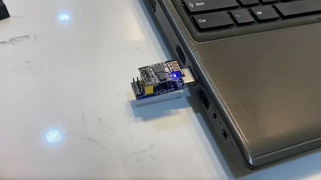
After finishing the coding part, we can upload the Sketch into ESP-01S using the USB programmer.
 |
| ESP-01S with USB Programmer connects to the computer. |
Wire Up
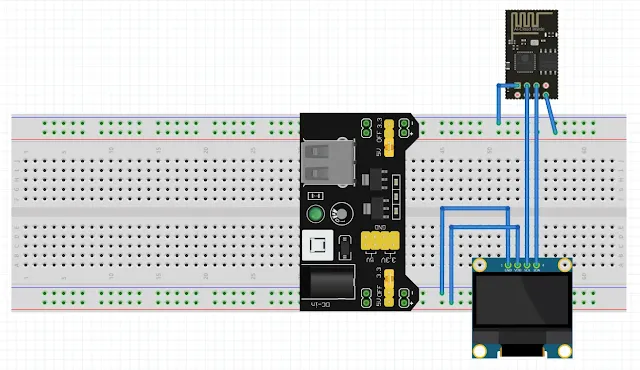
You can wire up the components according to the diagram below:

|
| YouTube subscriber counter schematic |
- Wiring between YwRobot Power MB V2 and ESP-01S
- YwRobot Power MB V2's 3.3V + ↔ ESP-01S's VCC
- YwRobot Power MB V2's 3.3V - ↔ ESP-01S's GND
- Wiring between YwRobot Power MB V2 and OLED Display
- YwRobot Power MB V2's 5V + ↔ Display's VCC
- YwRobot Power MB V2's 5V - ↔ Display's GND
- Wiring between ESP-01S and OLED Display
- ESP-01S's GPIO 0 ↔ Display's SDA
- ESP-01S's GPIO 2 ↔ Display's SCL
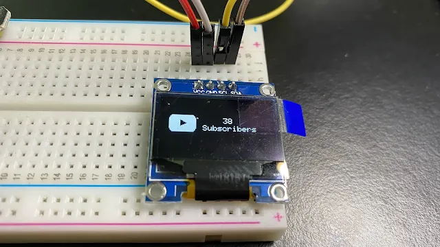
The Result.

|
| My YouTube subscriber count displayed on it |
 |
| YouTube subscriber counter in the invert display mode. |
Known Issues
The logo and texts may not align when the subscriber goes up and increase the digits.
 |
| YouTube Subscriber Counter in Simulator |
I'm not fixing this issue now. Because my YouTube channel still has a long way to go. I will fix it until I hit it.


%20with%20Rechargeable%20NiMH%20batteries%20and%20HT7833%20voltage%20regulator%20cover.webp)

